<Home> 26/07/2025

Synthesiser Build Process

Social media links: GitHub, Youtube, receive@zene.uk

About

Modules

The Build Process

The Final Product


The Box

Construction on the box began in July 2023. I had the pieces of the box cut out of a large 18mm plywood sheet, with the side ones cut using a router. The box was then assembled with large rounded screws along the left and right sides to give an industrial look, and beading along the inside to support the other edges. A thinner 12mm plywood sheet with a similar angled step shape was added to the middle inside the box. This was to provide extra support along the middle so that the racks that were to hold the modules would have less flex to them. Both of these steps were not carried out by me. I then sanded the outside, and applied a wood stain and varnish to get the look and feel I wanted.

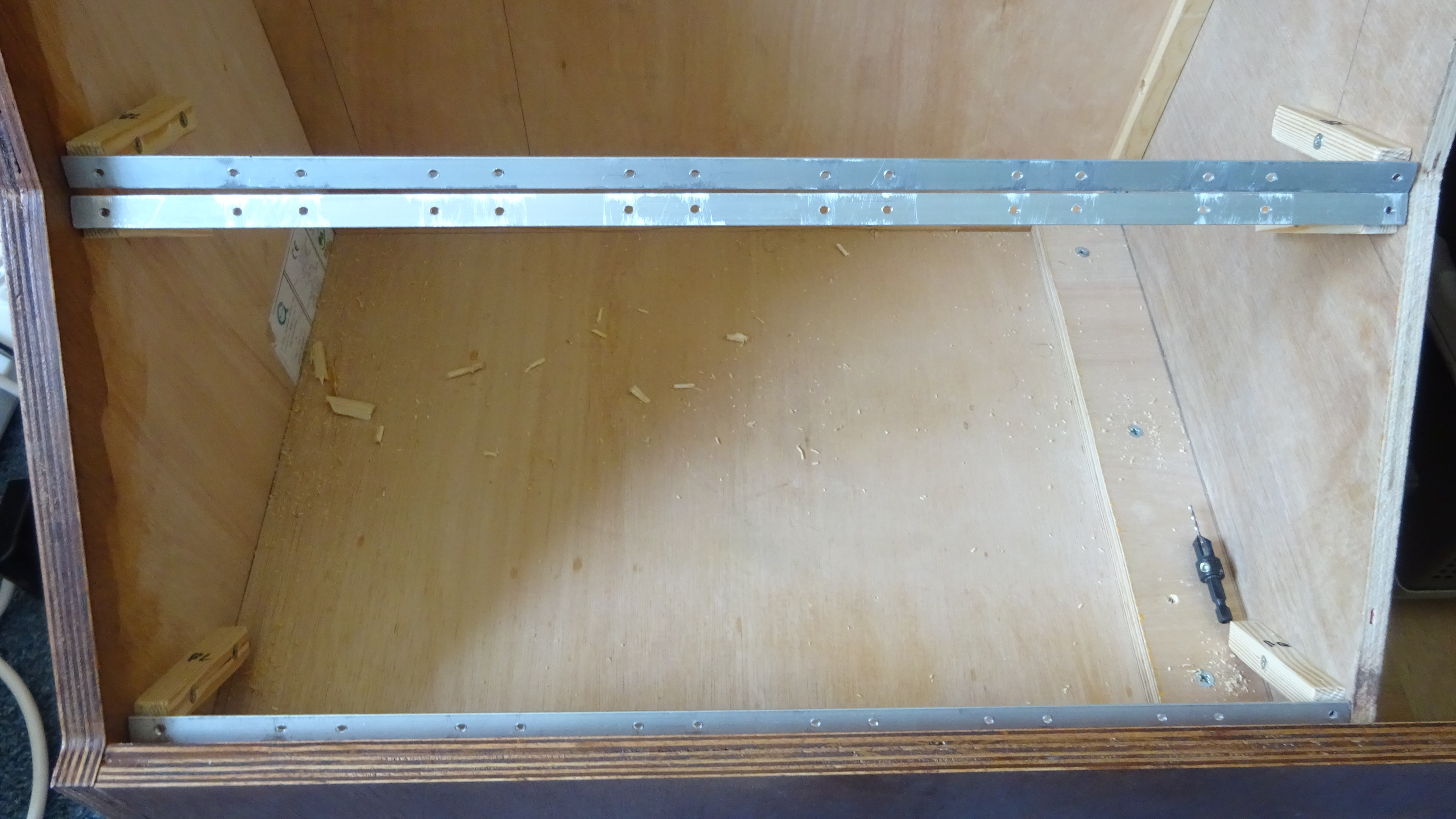
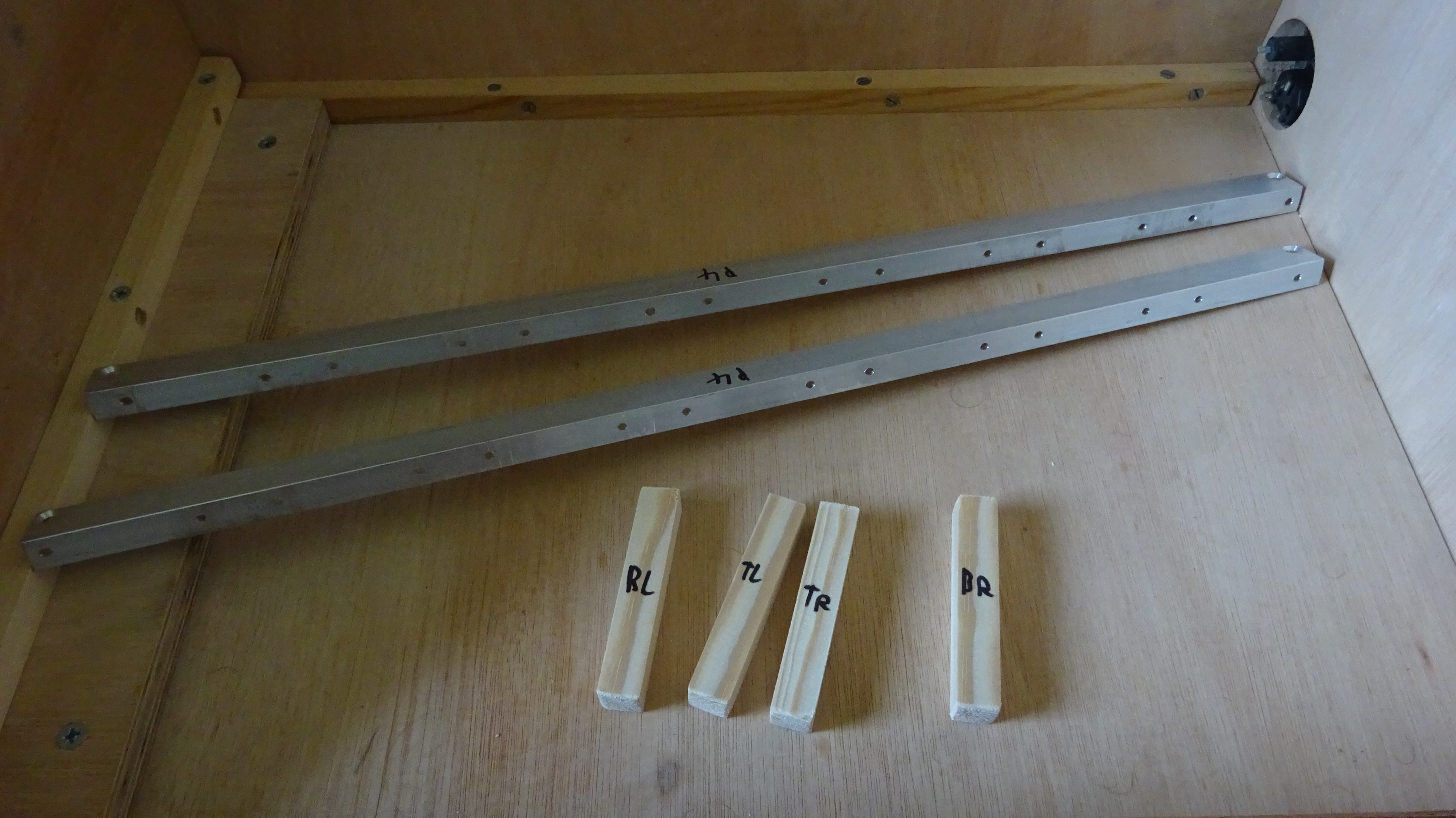
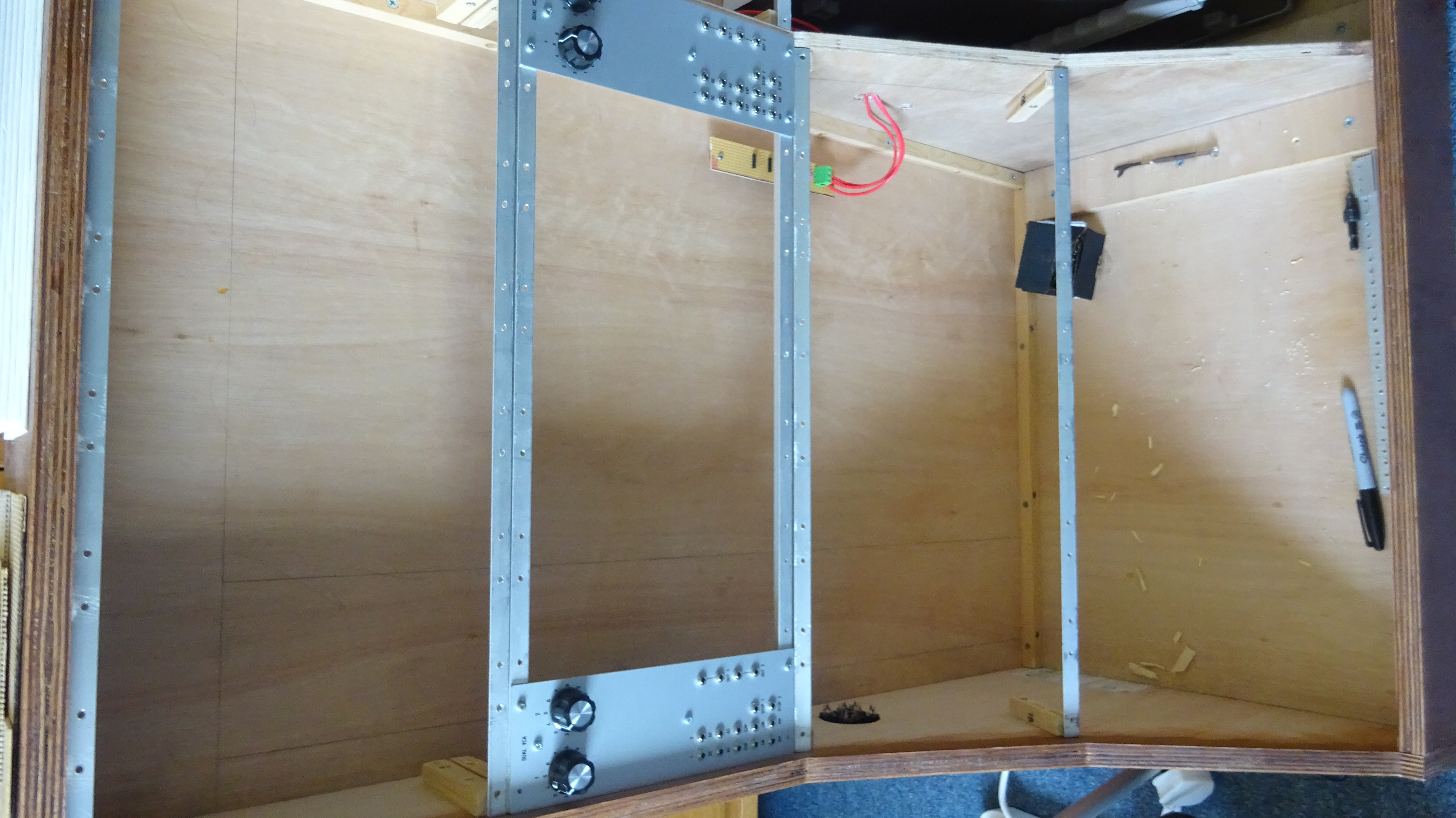
The plan for attaching the modules was to have metal L-shaped strips along the inside that the modules screwed onto. 
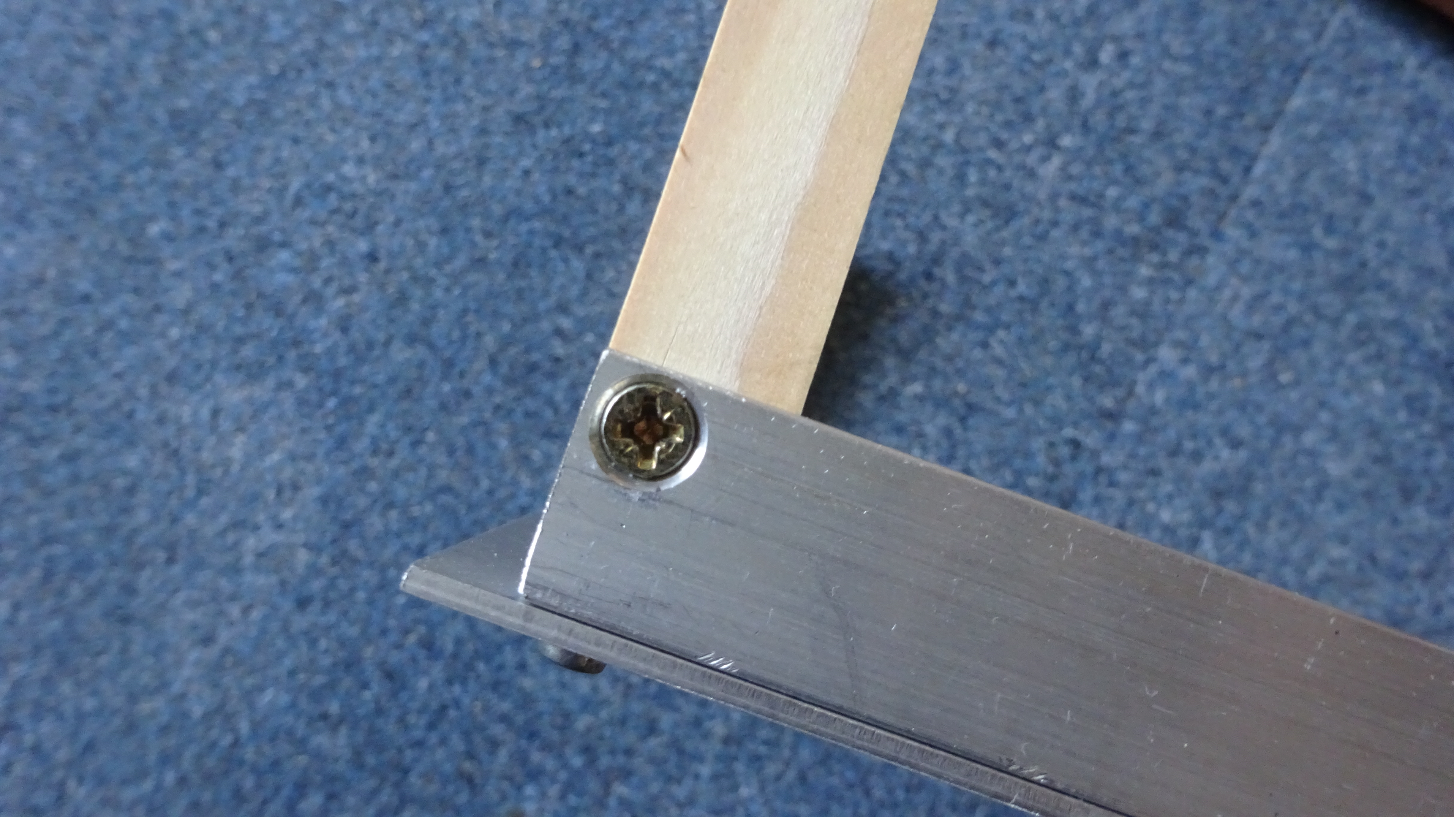
These would then be attached to small wood pieces at the edges, which were then screwed into the box from the inside. 
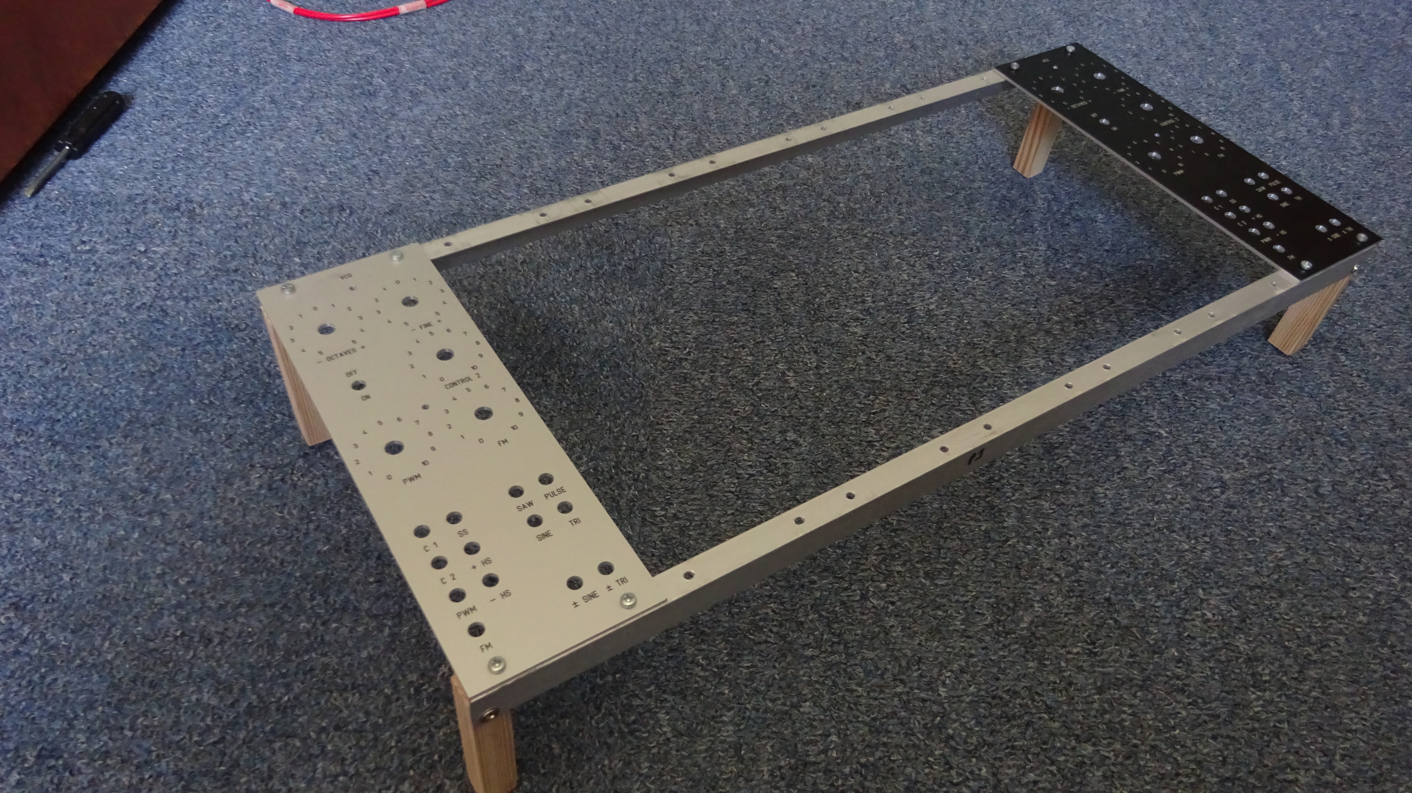
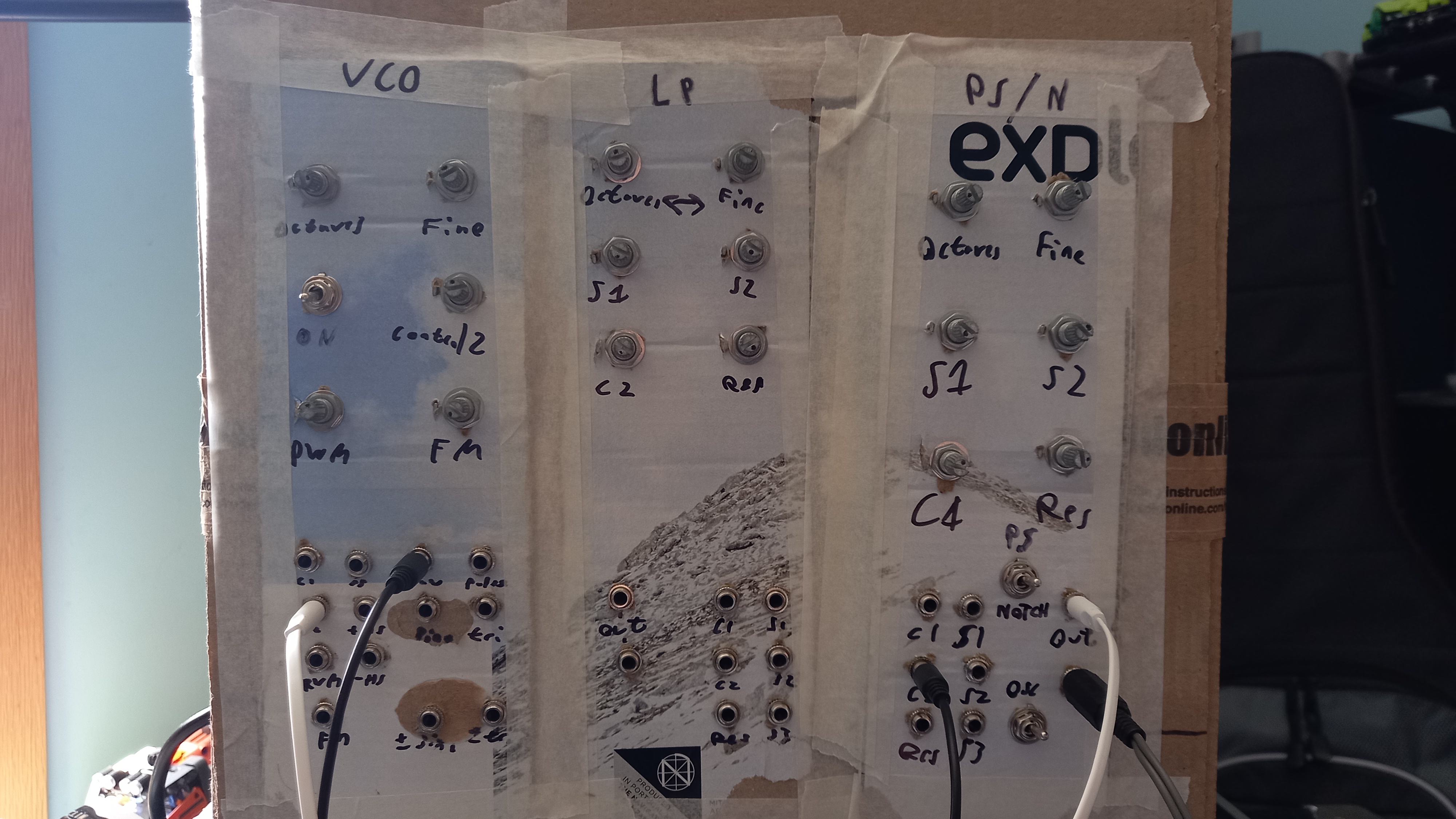
To insure that the spacing was correct for these racks, I attached the sample panels to the two pieces for a section as I installed it.

A slight oversight in the design ment that installing the rack mounts for the bottom row was extra difficult. The lip from the frame along the front of teh box got in the way of accessing the screws for attaching and removing modules. It also meant that when installing the bottom row of modules, I had to temporarily remove some of the screws attaching the rack to the box so that I could rotate them. This then forced me to install the entire bottom row before adding any modules to the next row up.


Building the Modules

The very first thing I built was a dual power supply. For simplicity I used the classic transformer voltage regulator design. As the specifications I was following for most of the modules used ±15V, that is was I stuck with.

I built the very first modules before I had ordered any of the panels, so I used cardboard temporarily. There were 3 modules that were built like this to prototype the construction method and circuits. I also used them to test the power supply as well. For fun I put all of this into a cardboard box and used that as a very small synth with the limited cables I had.

The construction process went through a few revisions, but I finalised it with this.
Use the flipped jumper wire image to add all the cuts to the tracks. Test each cut with the multimeter to check for shorts. Then add the main jumper wires, install the components, add solder bridges and final jumpers. Add the panel components to the panel and add all the inter panel wiring. Attach the circuit to the panel then wire the panel components to the circuit. The circuit test method I mention later.

There are a total of 55 modules in the synthesiser that I had to build. Each one took an average of ~5 hours to make, with a total of over 215 hours of soldering. The video shown is a timelapse at 64x speed of me construction most of the modules. The initial 3 and the split module were not recorded, and the panel work of the first 2 in the video are also missing. For most of 2024, I would get up a 6:00 AM to work on a module for an hour before school. And then on Sunday, I would spend most of the day working on another module. This meant I was building 2 modules a week.


Prototype Videos


Testing the Modules

There were only a few modules that actually functioned correctly first time after construction. The rest all had some issue I had to fix, which added at least a few more hours of work per module. Whilst testing the initial prototype modules, I had power supply shorting issues and there was one time a chip starting releasing smoke. After these expierences, I formed a thorough testing process to prevent further damage to my ICs.
I would first use a bright light through the stripboard and run a scalpel along the gap between each track to tidy up the board and check for solder bridges. Next I probed all the power input pins to check for shorts before powering up the module for the first time without ICs installed. Then I would add the ICs and do another pin short check. When powering up the module again, I would feel the temperature of the chips to make sure they weren't overheating before started to test the functionality of the module.

Many modules had some design issues which I had to fix and then form a rework of the stripboard layout that would still be possible with the permanent changes I had made in construction. There was also a module that I had copied the circuit wrong, so had many areas I had to redo. Various designs also did not function as I wanted, so I modified the circuit and construction to get the results I prefered. This was often just changing resistor values, but some change were more substantial.

The video shown was me using the wave folder module just after testing and getting it working.


Installing into the Box

For quite a while, whilst I was putting off working on the box, I attached all the modules I had onto a couple racks that had not been installed in the box. I then used this as a synthesiser for a bit, including recording the demo video in 2023. However, before I could start installing the modules into the synthesiser, I needed to attach power distribution boards into the box. This also required drilling a hole through the centre support board to allow for power wires to get from one side to the other. Various other things needed to be attached inside the box as well, including the power supply, spring reverb tanks and the midi module's circuit.